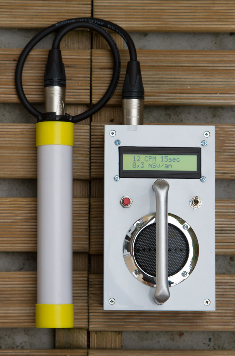
Geiger counter with SBM20 tube
I « rebuild » my Geiger counter, the SBM-20 tube was initially inside the box, so, i have put this one inside a 32mm diam plastic tube, for more convenience, wired through a XLR3 cable.
The LCD display alternatively, the « count per minutes » and result on: milli Sievert/year or nano Sievert/hour, you can switch off/on the buzzer, also 3 modes on measure are available, 15/30/120 secs.
This counter is from « Electronique-Pratique » n°368, a French electronic magazine. Shem, pcb, and PIC hex & C source code available. (Microchip compiler C18 v2.40/MPLAB 8.4)
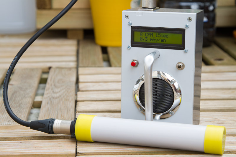 Geiger SBM-20 inside the plastic tube. « The quintessential Russian tube. Lower priced, and more sensitive to beta and gamma than most. »
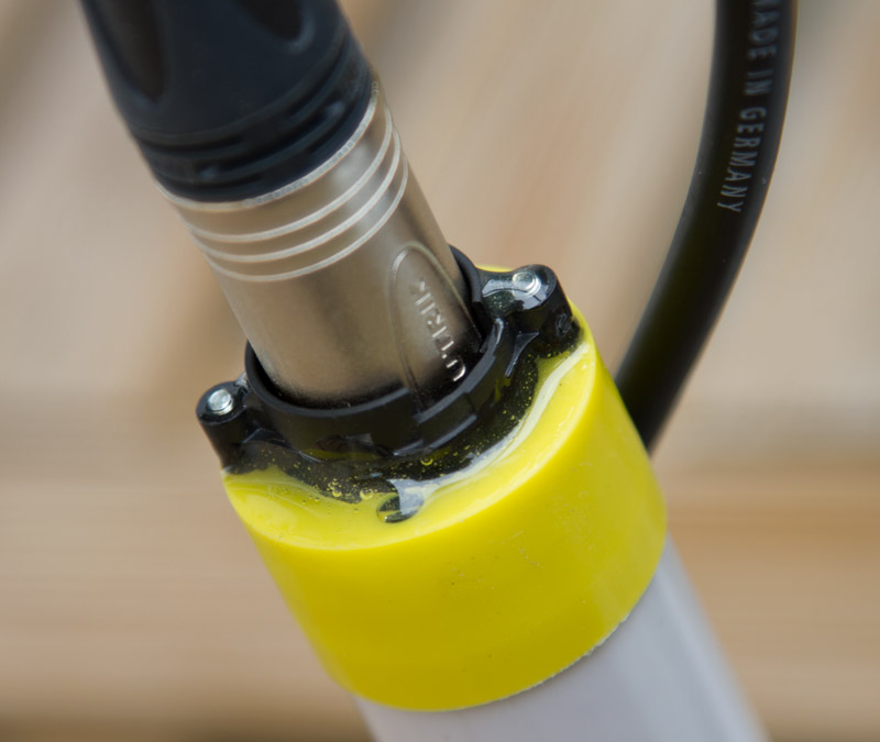 XLR3 connection, the connector is glued on the cap with resin epoxy glue.
Hello, would you please confirm if the Geiger_V13.hex, file is ok for PIC18F2550? Does the LCD show any message even without the SMB20 installed? Thanks in advance.
Hello.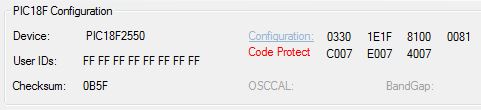
– Work with 1.5 or 1.3 hex.
– Check if configurations bits are correct.
– Check if the crystal work fine with oscilloscope or multimeter.
– Pic should start without SBM20.
– If any problem i can program pic for you.
Thanks for the files! I think I have a bad PIC, since I could not program a different file either. I’ve just bought a new one and will test it on the next week!
Hello, I’ve changed the PIC 18F2550 and the programmer. The PICKIT2 was not working fine. Now I successfully programmed it with PICKIT3. Despite of that, there is still no text on the LCD. All connections and components are double checked according to the project and are OK. I could not measure any oscillation in the Crystal, but I’ve already replaced it. Buzzer emits a tick each half a second and LCD blinks together. Any idea? Was there any correction in the original diagram? The prototype is still without the SMB20 tube. Thanks in advance.
Just a correction, I can measure clock now with the Oscilloscope, and it’s 4MHz, which seems correct.
There was no pulses in pin 13, so I disconnected R3 (1K), and the PIC started! LCD ok! I probably have some issues with the inductor or the MOSFET.
Problem solved, previous inductor was not ok. Once I replaced it, it’s all fine! Thanks!
Hello, just a few questions. My prototype is apparently working fine, but as I’m using a plastic case, I needed to put a metal shield over the high voltage section, since my hand was increasing the counting by the time I handled the case close to that area! This is now fixed. Besides that, when I connect the geiger tube cable to the case, it seems to be a little unstable, changing the counting for background, from 8 to 52 CPMs, in the same location. I think that it’s receiving a kind of interference, may be the cable that I used to connect the tube to the device. What do think about that? I see that you used a mike cable. Thanks!
Hello Eloy,
For security reason i use plastic enclosure du to the high voltage, and plastic tube for the SBM20,
but, mostly beta radiation are blocked with a simple paper sheet…
I have used « the ground » of the cable to connect the tube to the board.
Hello
When i program the pic with the program in the file you give it is not compatible with 18f2550 i am getting the error could you please Can you write me new program for this circuit (for pic18f2550)
Hello, it’s should work with 18f2550
try with http://www.f4huy.fr/wp-content/uploads/2015/08/Geiger_PIC_HEX.zip
also check fuse in your programmer
Hi
Thnks for updated version 1.5.
Unit running … 🙂
Regards