APRS Tracker, with DRA818V
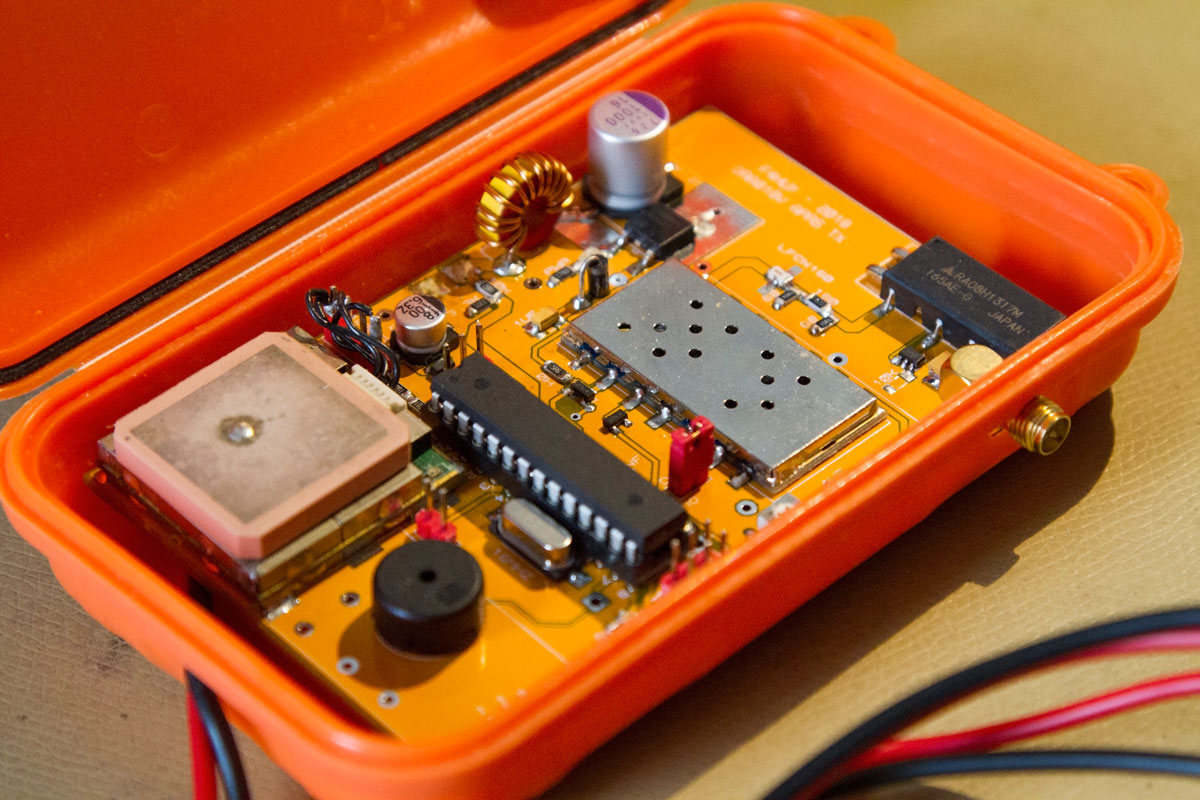
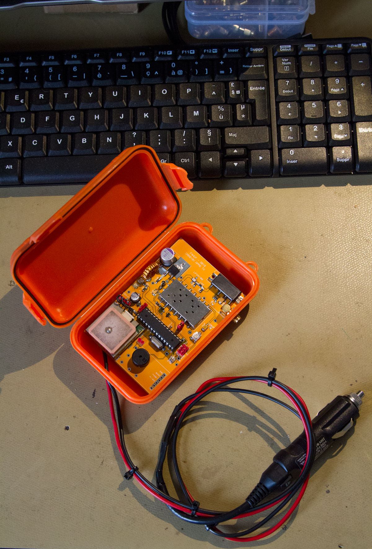
Currently testing and prototyping, based on DRA818V with Atmega328P and GPS EM406, RF out up to 8W with a RA08H1317M from Mitsubishi. It’s around the same design of this, but with some modifications on the Trackuino code, something like called « SmartBeaconing™« , in this case i try to send APRS frames only when the tracker move above or under certain conditions, like speed or movement.
I’m currently working on the final testing of the prototype.
Update 4/6/2018
Finally, the board is running fine, compared to the original version, the ADXL sensor, has been removed, RA07M1317M is replaced by RA08H1317M, better to managed, (and with more output power) assumed to be installed into the car, the GPS is powered directly by the positive 5v regulator.
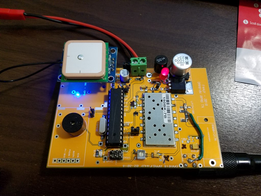
Power section: To avoid maximum of parasitic on the power line, L1, a 10uH choke, and 1000uf tantale cap.
DRA818v RF chip, GPS, MCU are powered through 7805 regulator (DPak 1.5A).
MCU: ATMega 328P from Arduino, classic 16Mhz crystal oscillator with 2x 22pf cap, modulation come out from MCU on pin 11, level can be adjusted with 20k adj resistor, 100nf in // on the filter is finally removed.
RF section: RA08H1317M give 9W of output power (@13.8v), this PA need only 20mw at input, so a attenuator is placed in front with a low pass filter from Minicircuit, LFCN160. The PA is powered directly from Vcc 13.8v, the Ptt line drive also the gate pin via a LP2981-3.3 regulator.
The DRA818V is programmed at startup on 144.800 mhz QRG, the power level is around 400mw. Resistor divider are insert on the dataline (3.3k/1.8k) since the MCU is 5v level serial. PTT is drive by a 2n7002k , PD line is a nightmare to drive, so for the moment this pin is tied to Vcc, so the module is always awake. This module need 4.5v max on Vcc, we use a 1n4007 (d2) diode to decrease value to 4.4v.
GPS: Old EM406 in my case, any kind of gps can be use, like the last Neo7, or 8…
Your APRS tracker will work only when you will be in your car, and no powered all the time, basically to manage the GPS power, i have put a 2n7002 in case to power off the unit, it was not a good idea, so i have tied directly GPS Vcc to +5v regulator.
Other components: Small buzzer is plug on pin 7, little melodies is hear when the board is powered, traffic LED is on MCU pin 8, power LED before 7805, LM60 temperature sensor on pin A0, VCC level is measured on pin A2, with 3.3k/10k resistor divider.
Components no needed on the prototype:
- 10k pulldown on LP2981-3.3
- Serial resistor on the lp2981 Enable pin => replaced by a strap
- 2N7002 on the power line of GPS => Read above, tied GPS Vcc to +5v
- 100nf on R/C filter => Remove it, better modulation quality
Sketch: Sketch for Arduino is based on https://github.com/trackuino/trackuino code, i have removed useless files, like buzzer, _pic32 file related ect …
You need to edit config.h to set some parameters like your callsign, and tx’ing delay,
#define APRS_PERIOD_HIGH 30 // define aprs send interval when your vehicle run
#define APRS_PERIOD_LOW 60 //1minute
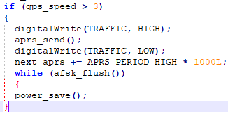
In the loop your can see, the read of speed variable, « gps_speed », this trick can do the txing depending of the speed. 
Harmonic: LFCN160 from Mini-circuit do the job, a little peak still present 289.600 mhz (harmonic type 2) @ -50db
Measures:
| Vcc | (I)A | P output | P consumption |
| 13,8 | 1.730 | ~9w | 24w |
| 12 | 1.630 | ~7.8w | 19.5w |
| 9 | 1.30 | ~4.5w | 11.7w |
| 5 | 0.6 | ~730mw | 3w |
| Tracking mode: 160ma |
| With GPS locked: 150ma |
| Tx @ 13,8v: 1,7A |
Improvements:
- GPS DATALogger: ADXL sensor was removed to replaced by a SDCard socket, this function is not implemented yet.
- Work on DRA818V PD line to improve power consumption.
- Do a TRUE SmartBeaconing™ , right now APRS broadcast is only depending of speed, if speed is above 3km/h, APRS packet is send every 30sec, else, every 60sec.
- Other idea ?
Download Schematic, PCB, Arduino sketch
Resources:
LP2981-3.3 Regulator
VHF RF DRA818V
MC7805CD2TR4G Regulator
RA08H1317M – Mitsubishi Electric
EM406 GPS
LM60 Temperature sensor


09/2018
One unit builded by John, KC2SFW (USA)
I have some extra pcb available, contact me

I know its only been a day, but hows the prototype going? Looking for a small but powerful aprs tracker, for my youngest son whilst he’s mountain biking on a hilly forest in Wales.
Hi Ian, code is almost finished, excepted, the ADXL335 part, not writed yet, i hope to test a pcb before the end of may
please keep me informed, would love to help beta test the module, will gladly help pay for pcb’s, modules etc. I used to be able to solder and dont mind digging the old metcal soldering iron out and singeing my fingers if that could help. I can program arduinos/pic’s and have done a little bit of programming
M0ODD/AC2ES
Hello, M0ODD/AC2ES
I’m waiting for my DRA818V
Nice work
Will you give it as pcb
Will gerber files be provided for pcb?
I’m certain of the price
TA2TQ 73
Hello dear om
Yes gerber will be available
The pcb prototype will arrive soon
Cost under 10$
hows this project progress?
hello Gunawan,
i have almost finished the pcb design last night, just need to check for error
now i’ll send to pcb manufacturing, hope got the pcb prototyp before the end of this month!
Hi
what is the latest situation
Hello,
When i’ll got little bit time to solder the pcb, this autumn, I’ll update the post
Hi
Is this board or design available?
Evan if you are not complete I would be interested in building it.
Hi Anton,
Just got the pcb yesterday, so i’ll try prototyping soon!
Le hasard m’a amené ici, j’adore ce projet. Je repasserai 🙂
@+
pcb reçu mais ya une merde au niveau de l’alim, donc en suspend, quand j’aurai le temps 🙂
Keep up the goog work, looking forward to the final results, an option to run the unit of batteries (looking to attach a unit to my sons bike to track him across the hills in Wales)
It’s the final result. You can run the board with an external batteries. I have discovered à little bug with the temperature sensor. Work to fix it.
I just built a prototype of this and it works great!
I’m using an external power amp instead of the ra08h1317m. Still need to work on the LPF.
I added « corner pegging » code to the smart beaconing.
Now to put it all on a PCB.
Thank you!!
don’t hesitate to share your corner pegging code , that, i can integrate the code in the project
Hello, we are currently building a prototype of this APRS but using GPS ublox neo 6m, is it possible? If so, could you give us some information on how to manage the code with the new gps?
Also, we are going to make a pair, which the other one will act as the receiver. Since your schematic is for transmitter, are there any changes for the schematic if we want to make the receiver side?
Thank you very much